Last year, Andriy Yeroshevych wrote about Roboscope’s journey from HoloLens to mobile. A lot has happened since. This is where the platform stands today.
The problem hasn’t changed
Inspecting a 100-meter wind turbine blade still means walking its length, finding defects, measuring their position along curved surfaces, logging dimensions by hand, and hoping the repair crew can relocate each finding from a written description. Five or more measurements per defect. Paper forms typed into ERP later. No shared coordinate system between inspection and repair.
The process is slow, error-prone, and expensive — especially when edge cases block production while photos bounce back and forth over email.
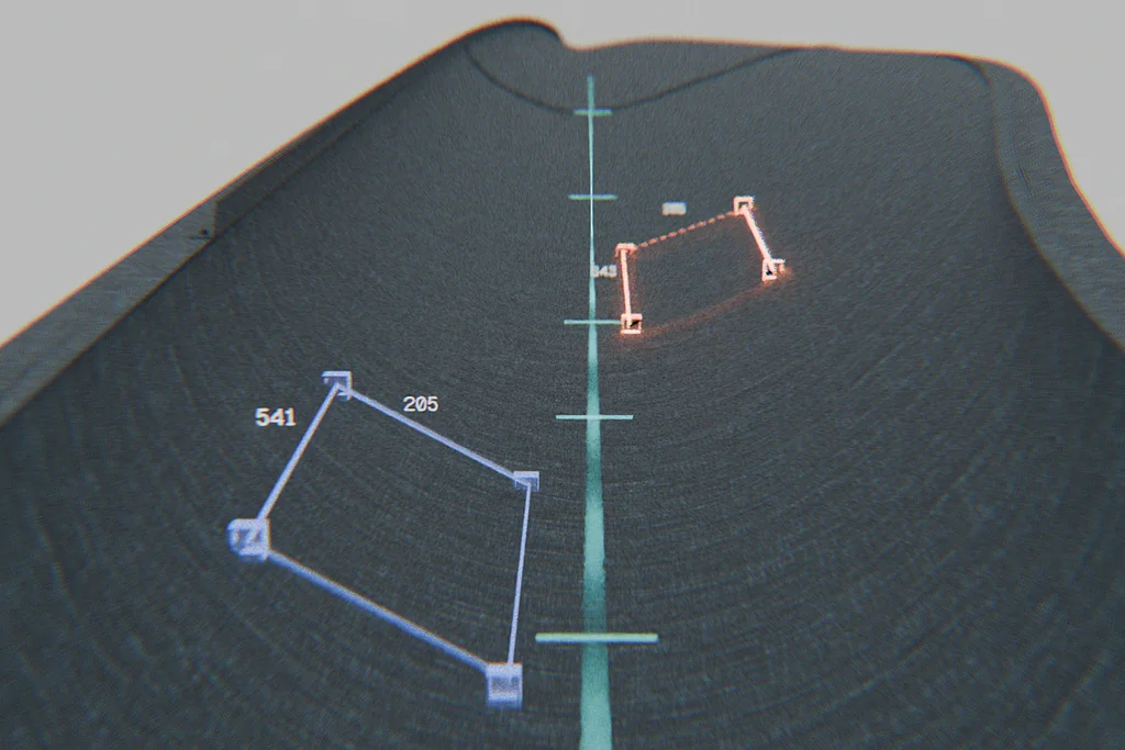
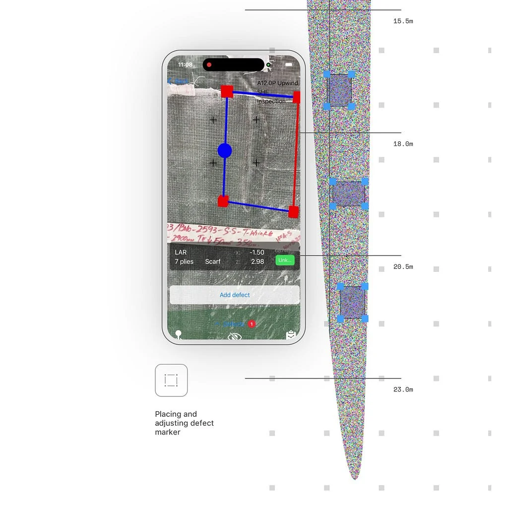
The core functionality solving these problems stayed the same. The inspector holds an iPhone, walks the part, and places digital defect markers directly on the physical surface using AR. Each marker captures defect type, spatial location, dimensions, and photographic evidence in a single session — no tape measure, no coordinate entry, no re-measurement.
New anchoring system
What has changed is how we anchor to the blade coordinate system. iPhone AR proved notoriously unreliable for tracking position over distance. The error accumulates as the user moves and spins out of control after roughly 10 meters from the origin. Even using the standard iPhone ruler in the 20–30 meter range, you will observe 1–2% drift — unacceptable for engineering teams.
To mitigate drift, we began anchoring locally using known reference points on the shell. External features of the production mould, QR codes placed at fixed locations in the passages around the mould, or a laser pattern from the overhead projection system are all suitable candidates.
The workflow is straightforward: before placing each defect marker, the inspector scans the nearest anchor point and then installs the AR marker. Within a 4–5 meter radius, drift stays in an acceptable range. In large-scale testing we demonstrated 45 mm positional accuracy at 95% confidence.
Layer-level intelligence
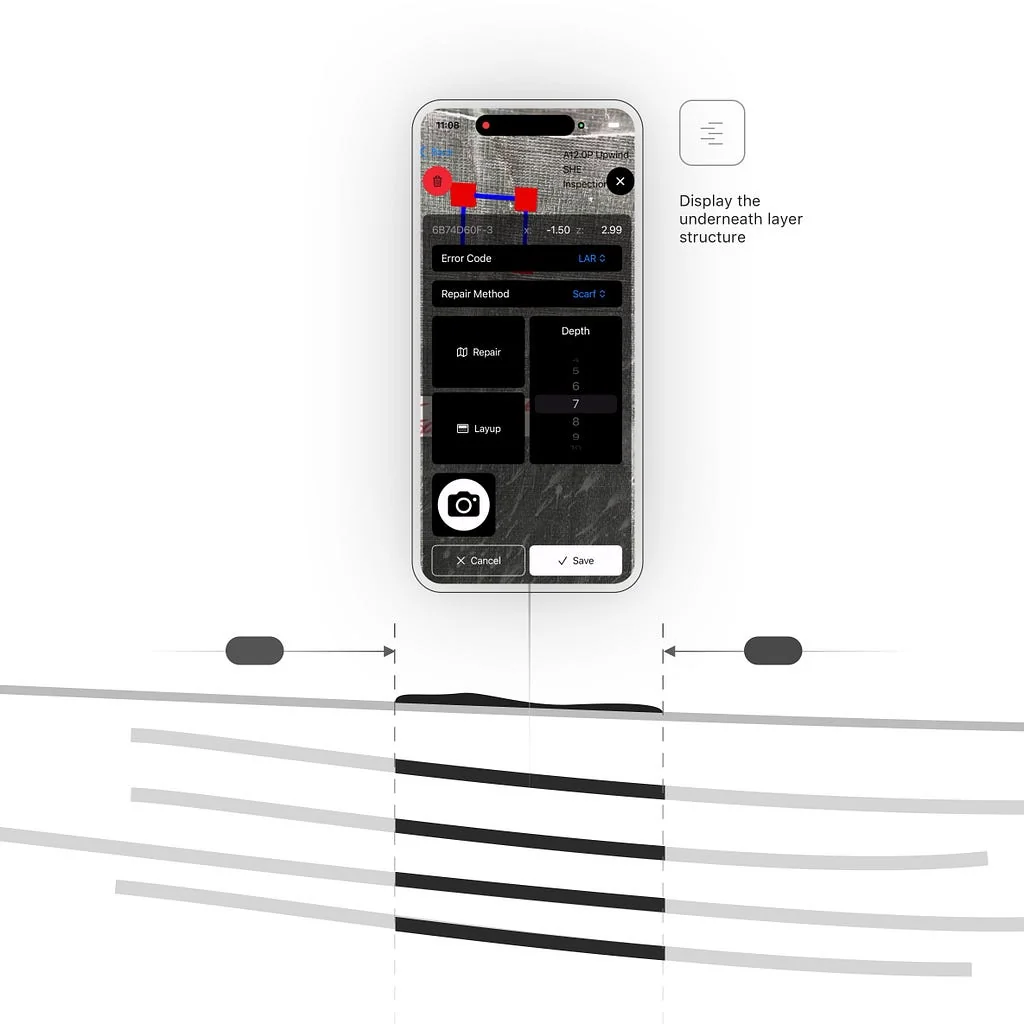
Accurate location unlocks real insights for repair teams. Every AR-anchored defect is automatically cross-referenced against the Layup Registration Table — the full ply stack at that exact surface coordinate. The system returns which layers are affected, their material and orientation, and a repair classification based on structural ply count. Engineers get a precise cross-section view without disassembly. Structural hits trigger automatic escalation.
Where we’re deploying
Roboscope was built for wind turbine blade QC, and that remains the core. But the spatial marking problem turns out to be remarkably similar in adjacent industries — large aerospace structures, marine and shipbuilding, construction, and NDT on any large surface. We’re actively exploring these with engineering teams who recognized the same pain.
What’s next
In the background, we are working on improving coordinate precision even further. But the main focus now is at the application level: what can we do with the spatial intelligence of defects on the blade to both repair faster and take corrective action in the future. A separate track — dedicated computer vision for defect detection and repair validation — we’ll write about separately.